
AZKN6129P - Key Parameters to Consider When Selecting CAN Bus Transceivers for E-Bike Systems
With the global emphasis on health and environmental sustainability, electric-assisted bicycles (E-Bikes) have gained tremendous popularity and have become an important means of transportation that combines exercise, recreation, and daily mobility. Thanks to continuous advancements in battery technology, E-Bikes now offer longer riding range and faster charging speeds, significantly improving the overall riding experience.
In addition, the integration of intelligent features has become a major highlight of modern E-Bikes. Functions such as built-in GPS, Bluetooth connectivity, and smart control systems enable real-time monitoring, positioning, and navigation while enhancing overall safety. Furthermore, lightweight designs and the expansion of charging infrastructure are accelerating the adoption of E-Bikes as a mainstream option for short-distance urban commuting.
Taking Taiwan’s smart city initiative as an example, the increasing deployment of YouBike 2.0E electric-assisted bicycles—and their utilization rate being nearly twice that of conventional bicycles—clearly indicates that modern users prefer energy-efficient, lightweight solutions suitable for short-distance transfers. This trend not only helps alleviate traffic congestion but also contributes to carbon emission reduction, aligning with the future direction of urban development.
However, when selecting a CAN bus transceiver for E-Bike applications, the following key parameters should be carefully considered:
A. Package
With the trend toward miniaturization in E-Bike designs, PCB sizes for motor controllers and display units continue to shrink, leaving limited space for CAN bus-related circuitry. Therefore, DFN-packaged CAN bus transceivers are recommended. For example, a DFN8 package with dimensions of only 3.0 mm × 3.0 mm can significantly save PCB space and provide greater layout flexibility.
B. Fault Voltage
Typical E-Bike system voltages include 36 V (with a maximum of 42 V) and 48 V (with a maximum of 54.6 V). As CAN bus connectors become increasingly compact, accidental contact between CANH/CANL and DC power rails may occur, leading to overvoltage damage. Consequently, CAN bus transceivers used in E-Bike systems are often required to support a fault voltage of at least 42 V, with 70 V being highly desirable to ensure compatibility with both 36 V and 48 V systems.
C. VIO Voltage Translation
With advanced semiconductor processes, MCU operating voltages have largely shifted from 5 V to 3.3 V, and even down to 1.8 V. CAN bus transceivers equipped with a VIO pin allow flexible I/O voltage matching. By directly connecting the transceiver I/O to 3.3 V or 1.8 V, designers can eliminate additional level-shifting components, achieving both space and cost advantages, as shown in Figure 1.
D. ESD / EOS Robustness
Compared to typical consumer electronics, E-Bike products are more susceptible to electrostatic discharge (ESD) during riding and higher-energy electrical overstress (EOS) events caused by charging cable insertion and removal. To reduce field failure and return rates, ESD specifications for E-Bike applications are often more stringent, sometimes exceeding IEC 61000-4-2 Level 4 requirements of 8 kV contact and 15 kV air discharge.
E. Temperature Range
Since E-Bikes operate outdoors for extended periods, thermal requirements are more demanding. It is recommended that designs support operating temperatures up to 125°C to minimize the risk of abnormal system behavior. Failure to meet temperature requirements may result in product damage, increased repair rates, and, in severe cases, loss of consumer trust and brand reputation.
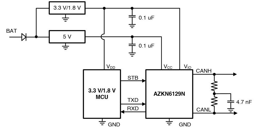
Figure 1. Reference circuit of AZKN6129N interfacing with 3.3 V or 1.8 V MCUs.
Driven by lightweight design trends, E-Bike modules continue to shrink in size, causing PCBs to be placed closer to enclosures. At the same time, advanced semiconductor processes make electronic components more sensitive to ESD events, leading to increasingly stringent system-level ESD testing requirements. At a minimum, products must pass IEC 61000-4-2 Level 4 8 kV contact discharge testing to simulate real-world ESD events encountered by end users.
For even harsher ESD/EOS requirements, incorporating appropriate protection devices at sensitive nodes, signal lines, and power inputs during the design phase can effectively safeguard the system before it enters the market. This approach helps prevent internal circuit damage or system lock-up caused by ESD/EOS events.
With over 20 years of expertise in wired transceiver design and ESD protection technologies, Amazing Microelectronic has leveraged proprietary technologies to develop the AZKN6129N CAN bus transceiver specifically for E-Bike applications. This device features a compact 3.0 mm × 3.0 mm DFN8 package to support increasingly miniaturized E-Bike modules. Manufactured using silicon-on-insulator (SOI) technology, the AZKN6129N offers a fault voltage rating of up to 70 V.
The CANH and CANL pins provide outstanding ESD robustness, supporting up to IEC 61000-4-2 12 kV contact discharge and 16 kV air discharge, along with enhanced EOS tolerance, as shown in Figure 2. Across the entire device, all pins are rated for 5 kV Human Body Model (HBM), 400 V Machine Model (MM), and 800 V Charged Device Model (CDM) ESD protection. Additionally, the device supports latch-up immunity currents exceeding 400 mA. As technology continues to evolve, Amazing Microelectronic remains committed to developing CAN bus transceivers that better meet market demands and can also provide customized solutions tailored to specific customer requirements.
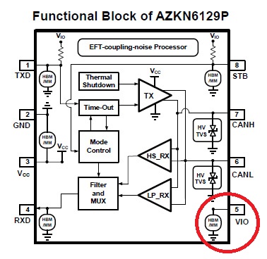
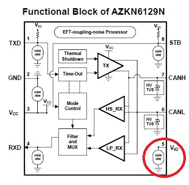
Figure 2. CAN bus solution for E-Bike applications from Amazing Microelectronic.
Features
- ISO 11898-2:2016 and SAE J2284-1 to SAE J2284-5 compliant for 2 Mbps and 5 Mbps CAN FD with wake up pattern wake up
- Fault voltage up to ±70 V for bus pins
- Integrated ESD and Surge Transient Voltage Suppressor (TVS) for bus pins
- TVS protection Immunities for bus terminals:
- ±12 kV IEC 61000-4-2, Contact Discharge
- ±16 kV IEC 61000-4-2, Air Discharge
- ±100 V IEC 61000-4-5, Surge (8/20 μs, 2 Ω)
Links
Copyright 2026 Macnica Galaxy International Limited