MAX32655: Ultra-Low Power MCU
Low-Power, Arm Cortex-M4 Processor with FPU-Based Microcontroller and Bluetooth 5.2
Integrates SIMO Power Regulation, Latest Generation Bluetooth LE 5, RISC-V Coprocessor

Product Details
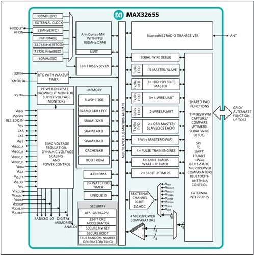
The MAX32655 microcontroller (MCU) is an advanced system-on-chip (SoC) featuring an Arm® Cortex®-M4F CPU for efficient computation of complex functions and algorithms that is qualified to operate at a temperature range of -40°C to +105°C. The SoC integrates power regulation and management with a single inductor multiple output (SIMO) buck regulator system. On board is the latest generation Bluetooth® 5.2 Low Energy (LE) radio, supporting LE Audio, angle of arrival (AoA), and angle of departure (AoD) for direction finding, long-range (coded), and high-throughput modes.
The device offers large onboard memory with 512KB flash and 128KB SRAM, with optional error correction coding on one 32KB SRAM bank. This 32KB bank can be optionally retained in BACKUP mode. An 8KB user OTP area is available, of which 8 bytes are retained, even during POWER DOWN mode.
Many high-speed interfaces are supported on the device, including multiple SPI, UART, and I2C serial interfaces, plus one I2S port for connecting to an audio codec. An eight-input, 10-bit ADC is available to monitor analog input from external analog sources.
The MAX32655 is available in a 81 CTBGA (8mm x 8mm, 0.8mm pitch) and a 60 WLP (3.13mm x 3.25mm, 0.35mm pitch).
Applications
- Asset Tracking
- Fitness/Health and Medical Wearables
- Hearables
- Industrial Sensors
- Wireless Computer Peripherals and I/O Devices
Features & Benefits
- Ultra-Low-Power Wireless Microcontroller
- Internal 100MHz Oscillator
- Flexible Low-Power Modes with 7.3728MHz System Clock Option
- 512KB Flash and 128KB SRAM
- Optional ECC on One 32KB SRAM Bank
- 16KB Instruction Cache
- Bluetooth 5.2 LE Radio
- Dedicated, Ultra-Low-Power, 32-Bit RISC-V Coprocessor to Offload Timing-Critical Bluetooth Processing
- Fully Open-Source Bluetooth 5.2 Stack Available
- Supports AoA, AoD, LE Audio, and Mesh
- High-Throughput (2Mbps) Mode
- Long-Range (125kbps and 500kbps) Modes
- Rx Sensitivity: -97.5dBm; Tx Power: +4.5dBm
- Single-Ended Antenna Connection (50Ω)
- Power Management Maximizes Battery Life
- 2.0V to 3.6V Supply Voltage Range
- Integrated SIMO Power Regulator
- Dynamic Voltage Scaling (DVS)
- 23.8μA/MHz Active Current at 3.0V
- 4.4μA at 3.0V Retention Current for 32KB
- Selectable SRAM Retention + RTC in Low-Power Modes
- Multiple Peripherals for System Control
- Up to Two High-Speed SPI Master/Slave
- Up to Three High-Speed I2C Master/Slave (3.4Mbps)
- Up to Four UART, One I2S Master/Slave
- Up to 8-Input, 10-Bit Sigma-Delta ADC 7.8ksps
- Up to Four Micro-Power Comparators
- Timers: Up to Two Four 32-Bit, Two LP, TwoWatchdog Timers
- 1-Wire® Master
- Up to Four Pulse Train (PWM) Engines
- RTC with Wake-Up Timer
- Up to 52 GPIOs
- Security and Integrity
- Available Secure Boot
- TRNG Seed Generator
- AES 128/192/256 Hardware Acceleration Engine
Evaluation Kits
MAX32655EVKIT

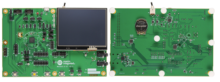
The MAX32655 evaluation kit (EV kit) provides a platform for evaluation capabilities of the MAX32655 microcontroller, which is an advanced system-on-chip (SoC). It features an Arm® Cortex®-M4F CPU for efficient computation of complex functions and algorithms, integrated power management (SIMO), and the newest generation Bluetooth® 5.0 Low Energy (Bluetooth LE), long-range radio for wearable and hearable device applications.
Features & Benefits
- External Bluetooth Antenna with SMA Interface
- Stereo Audio Codec with Line-In and Line-Out 3.5mm Jacks
- Digital Microphone
- 320 x 240 Color TFT Resistive Touch Display with an SPI Interface
- 128Mb Quad SPI Flash
- USB 2.0 Micro-B to Serial UARTs
- UART0 and LPUART Interface Selectable through On-Board Jumpers
- All GPIOs Signals Accessed through 0.1in Headers
- Access to the Eight Analog Inputs through 0.1in Headers
- 10-Pin SWD and RV JTAG Connectors
- Board Power Provided by USB Port
- On-Board 1.8V and 3.3V LDO Regulators
- MAX32655 Can be Solely Sourced by the Coin Cell Battery
- Individual Power Measurement on All IC Rails through Jumpers
- Two General-Purpose LEDs and Two General- Purpose Pushbutton Switches
Contact Me
ANStek-ADI Website:https://anstekadi.com
LIne:https://lin.ee/5gcKNi7
Facebook:https://www.facebook.com/ANStek3528
Sample apply & technical support:https://www.surveycake.com/s/dQ3Y2
email:marketing@anstek.com.tw
Links
Follow us on ANStek social channels
Related Site
ADI Product Microsite | ANStekADI.com
ANStek Web Portal | Linktree
©Copyright 2025 Macnica Anstek Inc.