
The Diplexer-Combined, Broadband Power Amplifier

Frequency multiplexers serve to either divide (demultiplex) the frequency spectrum into multiple sub-bands, or perform the complementary function of frequency multiplexing, wherein two or more sub-bands are combined to form a broader frequency spectrum. While diplexers are a 3-port component, their suffix correctly implies that they are comprised of 2 ports for the individual sub-bands, with the third port defined as the full band input or output, depending upon the orientation in which it is applied. While frequency multiplexers find a great many applications in passive filtering and channelization, it is also possible (and often advantageous) to utilize them as splitters and combiners for power amplifiers. Compared to traditional power splitters and combiners, multiplexers split and recombine in a frequency-selective manner that often affords lower loss as well as filtering that is not inherent to their power splitting/combining counterparts. This article discusses the basics of multiplexers and shows two different types of amplifier designs that use the same diplexer as the splitter and combiner. Finally, applications for each type of diplexer-combined power amplifier are discussed.
The Least Common Denominator of Multiplexers – The Diplexer
Multiplexers come in all shapes and sizes, and one of the most common architectures for their fabrication is comprised of suspended substrate stripline technology, as described in Mini-Circuits’ Understanding Suspended Substrate Stripline Filters, dated April 26, 2022.1 Many multiplexer configurations are possible by combining filters with lowpass, highpass, and bandpass filter characteristics. As mentioned at the outset, the simplest multiplexer configuration is the diplexer, and the simplest diplexer is the lowpass-highpass realization shown in Figure 1.
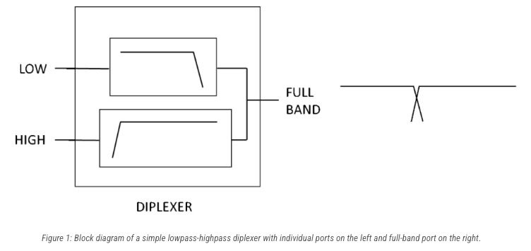
To fully define even the simplest of diplexers, several more characteristics are required. The nature of the stopband is important, since it may be reflective or absorptive. Additionally, the full-band output can be contiguous, as shown in Figure 1, or noncontiguous, with a gap introduced between the lowpass and highpass outputs. Finally, the highpass section is generally open-ended, extending beyond the upper operating frequency, but may be closed or include a clean-up lowpass filter, technically making the upper section a bandpass.
N-way multiplexers of greater sophistication often have multiple bandpass sections inserted between the lowpass and highpass sections. These bandpass sections can be narrowband or broadband, and for argument’s sake let’s assume that the inflection point between narrowband and broadband is octave bandwidth.
Mini-Circuits’ Diplexers
Mini-Circuits has designed and produced dozens of diplexers over the years, many of them using suspended subsrate stripline technology. A version of the ZDSS-3G4G-S+ designed specifically for handling 25W RF input power per port, the ZDSS-3G4G-3+ is a lowpass-highpass, reflective, contiguous broadband diplexer with a crossover frequency of approximately 3.45 GHz. 25W per port makes for a robust combiner, but this diplexer can also be utilized as a splitter and tuned back-to-back when splitting and recombining. Often times, however, the splitter is made much smaller and lower in power to meet SWAP-C requirements.
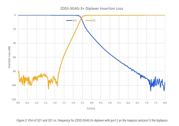
The frequency response characteristics of each of the ports of the ZDSS-3G4G-3+ diplexer are shown in Figure 2. Notice how the diplexer full-band response is contiguous. The crossover region just below 3.5 GHz is also very well-behaved, dipping little more than 3 dB for both the lowpass and highpass sections.
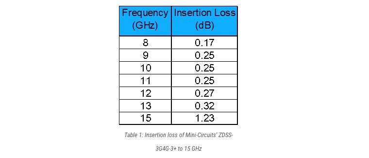
Although Figure 2 is plotted only to 8 GHz, the open-ended nature of the highpass section enables the diplexer to operate much higher in frequency. Table 1 below lists the insertion loss of port 3 to 15 GHz, where measurement itself is truncated.
The Diplexer-Combined Power Amplifier – Band-Specific
Diplexer combining two amplifiers in frequency is superior to frequency combining using power splitters and combiners because of the 3 dB theoretical loss that power splitting and combining entail, plus additional insertion loss. Furthermore, it is very difficult to achieve wideband performance from power splitters and combiners themselves, certainly not close to what can be achieved through multiplexing. In the case of the ZDSS-3G4G-3+ diplexer, mid-band insertion loss for the lowpass section is only 0.17 dB at 1.75 GHz and for the highpass section only 0.24 dB at 6 GHz.
Higher order, n-way multiplexers utilized to combine amplifiers can be comprised of narrow bandpass sections to filter harmonics, even the second harmonic if the sections are sub-octave. Additionally, lower order amplifier intermodulation distortion (IMD) can be inherently filtered by a narrowband multiplexer, particularly 2nd order and often times 3rd order depending upon channel separation.
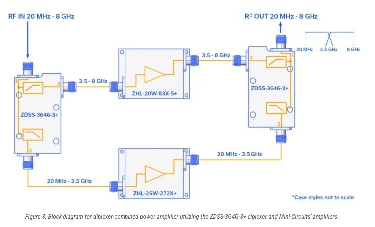
One example of a diplexer-combined amplifier is shown in Figure 3. The lowpass power amplifier is the 25W, 20 MHz to 2700 MHz ZHL-25W-272X+. Note that this amplifier rolls off above 2700 MHz, well before the contiguous diplexer reaches 3.45 GHz. On the highpass side, the ZHL-20W-83X-S+ handles the amplification and pushes 20W from 4000 to 8000 MHz. Similiar to the lowpass side, this amplifier does not reach the 3.45 GHz crossover frequency either. Consequently, this design would be considered noncontiguous due to the choice of amplifiers.
The Diplexer-Combined Power Amplifier – Broadband and Contiguous
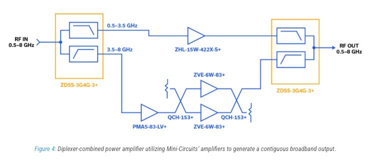
To fashion a contiguous diplexer-combined amplifier with a crossover frequency of 3.45 GHz, we swap out the amplifiers from Figure 3, perform power combining on the highpass section amplifier design to increase power, and arrive at the design shown in Figure 4. In this configuration, the15W, 600 to 4200 MHz ZHL-15W-422X-S+ supports the lowpass section and highpass side is managed by the PMA5-83-LV+ MMIC driving a pair of 6W, 2000 to 8000 MHz ZVE-6W-83+ amplifiers combined in quadrature with the 25W, 3000 to 14500 MHz QCH-153+ stripline quad. In this design, plenty of overlap exists in the frequency performance of the amplifiers for contiguous operation. Back-to-back tuning of the diplexers is often performed to achieve optimum frequency response in the crossover region, and well as amplifier insertion phase matching to ensure the same.
One example of a potential application for this contiguous amplifier is in the commercial wireless space. Imagine that a major telecommunications network operator wanted to transmit their 5G LTE bands. The sub-6 GHz bands used by this telecommunications network operator are n2 (1900 MHz), n5 (850 MHz) n66 (1700/2100 MHz) and n77 (3.7-3.98 GHz). All these bands except for n77 would get amplified in the lowpass section, and their second harmonics (4th harmonic in the case of n5) would be attenuated to a degree, by virtue of the isolation between diplexer ports. The 3.7-3.98 GHz portion of n77 used by this particular telecommunications network operator would get amplified smoothly through the highpass section and the entire transmission would include all of their 5G LTE bands in one spigot and direct them to one antenna.
Contiguous Diplexer-Amplifier Cascaded Gain
- Amplitude-only, represents the optimum case
- Advantage is that amplifiers need not be so broad, inefficient, harmonic-laden, and distributed, costly in nature
- Phase anomalies can be constructive or destructive
- Tuning diplexers back-to-back is the best approach
- You then need only equalize the insertion loss of the PAs in the crossover region
- Dips as minimal of just a couple dB are possible
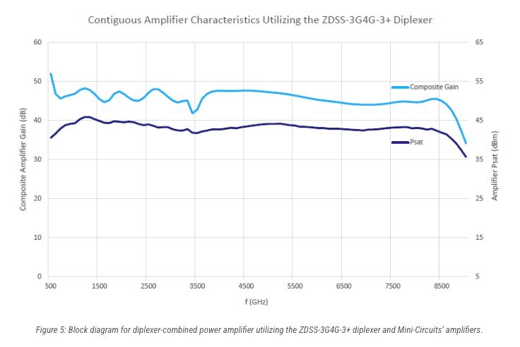
Figure 5 shows an ideal estimate of the performance of the contiguous diplexer-combined amplifier for both small signal (amplifier gain) and saturated (Psat) conditions. Note that this broadband performance is ideal because only amplitude terms were used in its calculation, and should be considered for informational purposes. In reality, phase disparities in the crossover region will not always lead to constructive addition of signal amplitudes.
Another example for the use of this diplexer-combined, contiguous broadband amplifier is in EW applications. Most often, amplifier harmonics and IMD are of lesser importance than full-band frequency coverage. As an aside, note that our contiguous design starts at around 500 MHz, which is a good starting point for EW and jamming applications, as frequencies below 500 MHz will generally be handled differently and with different radiating elements.
For EW applications above 500 MHz, where you want instantaneous control of the entire spectrum for a variety of countermeasures, the contiguous, diplexer-combined amplifier is a good starting point.
Power Limitations for Diplexer-Combining
Our focus has been utilization of the ZDSS-3G4G-3+ diplexer, which handles 25W per port. Suspended substrate stripline multiplexers in Mini-Circuits’ lineup of custom products can certainly handle greater power levels than this, but limitations do exist. Dielectric breakdown of air (arcing) can occur when field strengths intensify at sharp corners on copper traces. Generally a corona will be visible before an arc occurs. Resonances associated with localized voltage maxima can lead to arcing as well.
It Has Been Nice Multiplexing and Amplifying Together
In this article we introduced multiplexers and boiled them down to their simplest realization, the diplexer. The ZDSS-3G4G-3+ diplexer was discussed in detail and the magnitude of its transmission characteristics was plotted versus frequency. Two separate diplexer-amplifier designs were shown, a noncontiguous and a contiguous. For the contiguous version, applications in the commercial wireless and EW space were described. Finally, power limitations for suspended substrate stripline multiplexers were discussed.
References
Contact Us
Mini-Cicuits Official Site: https://blog.minicircuits.com/
Contact Macnica Anstek (Taiwan Distributer) for support: marketing.anstek@macnica.com
Links
Follow us on ANStek social channels
Related Site
ADI Product Microsite | ANStekADI.com
ANStek Web Portal | Linktree
©Copyright 2026 Macnica Anstek Inc.